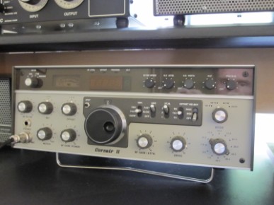
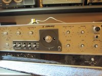
This is my vintage 1990 Ten Tec Corsair II. It is the most natural sounding CW radio in the world. With the 2.8 khz Inrad filter it also has outstanding receive audio on SSB.
The one shortcoming of this transceiver was always the main tuning mechanism which was prone to drift, small frequency jumps, and coarse tuning. With the installed N4YG solid state PTO, the stability is greatly improved, the fine tuning has extra precision using an optical encoder, there is SPLIT operation, RIT offset, and A/B VFO registers.
Here is a short video to display the improved tuning action.
TenTec sells their large knob from OMNI 5/6, and Orion which is the exact size for Corsair II with the skirt overlayed. The video shows the stock knob.
Conversion of the transceiver is described below:

Quick summary of my installation - from memory.
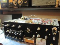
Remove all knobs from the front panel, unscrew the mic connector, SPOT, and unscrew the four phillips screws holding on the front panel.
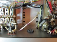
Remove the old PTO - cut the 4 wires and the coax. You only need the 8 volt line for the new DDS board.
Cut a keyhole in the Corsair II frame using a nibbler, hack saw, and file.
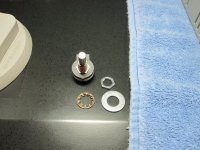
Mount the encoder to the Corsair front panel.
The SPOT switch is very easy to melt - tin the switch leads, tin two 8 inch wires and tack solder them.
While there, remove the s-meter, lamp, and shield and cut the wires off the OFFSET pot. Offset pot left lug is 5V input from one connector, center lug is RIT wiper, right lug is RIT ground from different connector.
Put the front panel back together.
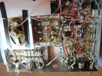
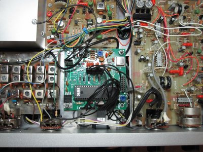
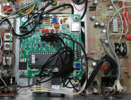
Drill three holes in the chassis for the DDS board, bolt comes through top side of the radio, lock nut on your side, then a spacing nut, then the DDS board, then a ring type lock washer and the bolt to secure the board. Connect the wires per the instructions provided.
Some tips - take power from the 8 volt line that was going to the PTO. It works even better than 12 volts and you have to go a long way to get 12 volts from the chassis.
Take the "R" voltage from the RF GAIN control yellow wire - close and handy. This is the wire that tells the DDS if the Corsair is in transmit.
When you power up for the first time you need to tune the main VFO to a signal then stop and rotate the OFFSET control through its range to hear where the center or deadband is. Center knob at 12 oclock there. Also, rotate offset full right or full left should turn the RIT OFF for you. Its nice to have some way of knowing when you are centered.
SPOT control - one lead splices to DDS control line, the other to the ground on the AF Gain control.
I took the power connection GND lead, tinned the end and bound under a nearby screw. I used the original coax line to the PTO to splice the DDS output.
For LEDS - go into the top area behind display and clip the wire just before it enters the connector and splice the DDS SPLIT LED into the jumper plug, let the old wire hang loose or it wont work. The OFFSET is the next to last wire on the plug but check it.
The instructions suggest that there should be more than one LED drafted as indicators, I found all but the "SPLIT" led to be redundant, and only wired the OFFSET led on the Corsair to the SPLIT indicator from the DDS.
Joe, N4YG went the extra mile in providing slide on connectors for every function on the board. This makes wiring a snap and any future changes to the board a simple unplug and replace action.