Softrock Ensemble III Construction notes.
The Ensemble III is a high quality kit, I just finished mine. Being an HF CW guy and a kit builder, I wanted to get a view of the SDR trend at a reasonable cost. What a great receiver, I cannot believe the value in Tony's kits.
If you are new to this, here are some helpful notes from my project:
I printed the INVENTORY pages, scotch taped the parts over their picture then wrote the part ID's there. Example 390pf Caps I wrote C9 C11 C22 C23 and later scratched each one off when used. This is especially useful for the resistors. I didn't tape IC's or transistor for ESD reasons.
Using this method soldering goes real fast, no need to identify or locate a part from heap, no stopping for wind and tin, just pluck - place - solder.
I soldered using 15 watt grounded tip IC iron and had a 40 watt iron for a few large parts like the BNC.
SMT parts can be nicely soldered using a MG Rosin Flux Pen if you are steady and have (a minimum 2X zoom or reading glasses) and a bright light like
an OTT-Lite. Solder wick is also essential.
- Flux the pads, for a SMT resistor, an IC, or even the tiny U2.
- Place part precisely with toothpicks, the flux will stick the part to PCB.
- First put a tiny amount of solder on the iron tip, then touch one pad but dont touch the part itself.
- The solder will jump from iron tip to find the flux and will the tack the part without moving it.
- Put a tiny amount of solder on the iron tip then touch the other side of the part and PCB, heat the joint, draw iron away.
- Put a tiny amount of solder on iron tip - press into the tacked side of the part and PCB, heat the joint, draw iron away.
- Depending on the SMT part, load more or less solder on the tip, this is the critical thing.
- When the iron has solder on the tip, two hands can be used to guide the tip.
- My Si570 was scotch taped to the PCB with one side exposed to tack the first lead, removed tape and soldered the rest.
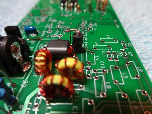
T3 can be a little fun, I mounted the ferrite core using double sided foam tape. I used a small insulated wire with a solid center to slide the ferrite beads over. Strip the wire on both sides of the ferrite beads, bend one side over, and solder the other side to the PCB. There is only one pair of leads coming out of one side of T3, solder these first. On the other side of T3 there will be two pairs coming out, a 3T (3 turn) pair and a 5T (5 turn) pair. The PCB has a white label for "1" and "4". One of the 3T ends and one of the 5T ends, doesnt matter which, go in the center unmarked holes. Remaining 3T end solders into "1", remaining 5T end goes through two ferrite beads and solders into "4".
SPECIAL CARE
- It is easy to cross mount R10 and R11 resistors in error.
- R35 and R36 each mount differently - note this!
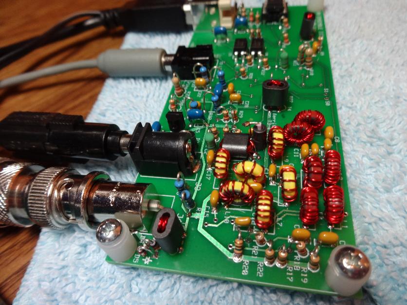
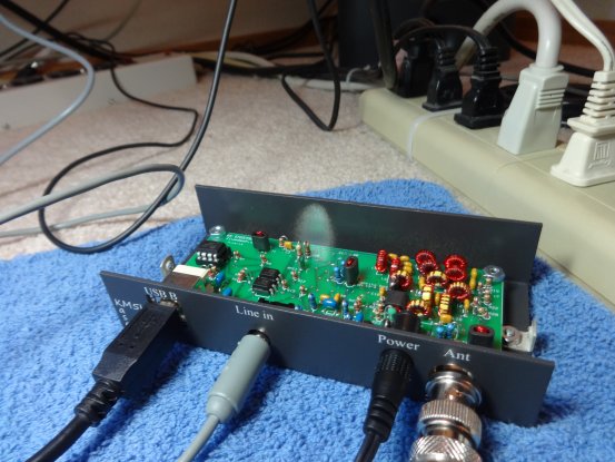
- D4 and D5 dont have circles on the PCB for mount. See picture below (lower left near BNC connector) to confirm orientation.
- U4 and U5 straddle split PCB grounds and will appear inoperative in LO final test if incorrect GROUND used to measure voltage at R12 and R13.
- None of the Voltage readings in the test phase were very precise for me everything was 2.5, 3.3, or 5 volts using my multimeter. Pins 3 and 11 of U7 have AC on them and may not be readable by your multimeter.
- At final assembly visual inspection make sure all SMT 1206 capacitors were used with only one possible extra to spare.
My ensemble III works great now but initially I had a wall wart supply for the 12v and that worked for the build but not for operation, it introduced noise into the receiver. Find and use your most advantageous 12v solution, RF chokes may be needed on this line.
Be sure to see this after building your kit: https://sites.google.com/site/g4zfqradio/more-on-ground-loops-and-audio-settings
I am really impressed with the operation of this receiver, it is very close in performance to my HF transceivers and I really like that the
preamplifier was added for the higher frequencies.
=============================================================
Ensemble III Toroid pre-wind cross reference table
=============================================================
For those that want to wind and tin before PCB assembly.
Wind the toriod, tin leads, then tape each one to a paper writing
PART ID next to it. I use the hot solder blob technique to tin the leads.
I don't scrape or sand the thin wire.
After all are wound, just pluck and place during assembly.
Toroid Color / Part ID / Turns / Wire Gauge / Direction / Wire Length
RED L01 - 40T Thin CCW 18" * Some overwinding needed
RED L02 - 28T Thin CW 12"
RED L03 - 40T Thin CW 18" * Some overwinding needed
RED L04 - 24T Thin CW 11"
RED L05 - 12T Fat CCW 7"
RED L06 - 24T Thin CW 11"
YEL L07 - 19T Fat CCW 9"
YEL L08 - 10T Fat CW 6"
YEL L09 - 19T Fat CCW 9"
YEL L10 - 11T Fat CW 7"
YEL L11 - 6T Fat CW 5"
YEL L12 - 11T Fat CW 7"
With RED or YELLOW side facing up, winding starts at 180 degrees on donut and
winding continues through 270 degrees using up the left side of the core ...
Holding a 2 inch part of the wire and then passing the long end of the wire through the donut:
CW = first pass through the donut is going away from you.
CCW = first pass through the donut is coming toward you.
The parts will work with any wind direction but they fit in their space on the board better if direction is used.
It is a good idea to pre-wind and tin T01, T02, T03, and T04 parts at this time as well.
======================================================================================
Loading Ensemble III Software
These are the steps I performed in sequence for loading the Ensemble III software using
Windows 7 Home professional, logged on as Administrator.
======================================================================================
Loading software for SoftRock Ensemble III testing and operation.
1. Run All in One Certificate/USB driver Installer
- PE0FKO-USB-Driver-Installer http://pe0fko.nl/SR-V9-Si570/PE0FKO-USB-Driver-Installer.exe
This will install a certificate in the computer and prepare the computer to accept the Ensemble III USB device when it is plugged into the USB port.
2. Run CFGSR installer
- Install CFGSR_V2.6 http://pe0fko.nl/CFGSR/Install_CFGSR_V2.6.msi
CFGSDR is used to setup the Si570 processor during the build.
3. Rename C:\PE0FKO_Driver\PE0FKO-USB-Driver\x86 libusb0_x86.dll to libusb0.dll
- Copy this libusb0.dll to OS(C:) Program Files(x86) CFGSR
This works for my configuration but others may need to find their own DLL in one of the other
subfolders under C:\PE0FKO_Driver\PE0FKO-USB-Driver.
4. Install HDSDR Program
- HDSDR 2.7 http://www.hdsdr.de
- Copy libusb0.dll from OS(C:) Program Files(x86) CFGSR to OS(C:) Program Files(x86) HDSDR
HDSDR is the one of several programs that I chose to operate the Ensemble III receiver after it is built.
5. Copy ExtIO_Si570.dll from CFGSR to HDSDR folder
- Copy OS(C:) Program Files(x86) CFGSR ExtIO_Si570 ExtIO_Si570.dll to OS(C:) Program Files(x86) HDSDR ExtIO_Si570.dll
After you have done this there will be a button "ExtIO" on the HDSDR window that will call up the CFGSDR utility program anytime you need it.
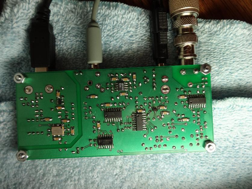
After the Ensemble III is complete, first check is to make sure there are no ground loops (See photos below.)
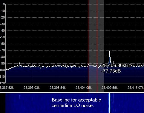
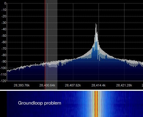

The Ensemble III can be sensitive to the power supply if it is an AC to DC converter. Less than 100ma is needed to operate the device. If you are seeing too much noise at the center of the display, experiment with differing 12v sources, even a 9v battery will power the Ensemble for testing purposes.
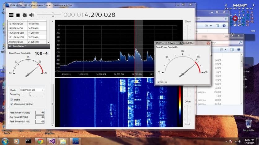
SDR# S-Meter